Tag Archives: Victorian Railways

T-TRAK Modules – The single mainline track modules, part the 13th – more work on the station platform.

Well after quite a few months I am back at the keyboard and updating on the VR Branch single track T-TRAK modules.  The last installment (Part the 12th) showed the platform walls being put in place along with a styrene sheet top for the platform. This sheet is recessed below the platform edge so that scenic material could be spread over the top. As I thought through the overall shape of the land around the platform and spent a few hours researching photos of smaller rural stations I ended up trimming the styrene sheet back quite a bit to allow a good amount of sloping ground on the road side of the platform while keeping enough of it to place the station building on a level surface. I have a small supply of blue EXTRUDED polystyrene insulation foam and made use of it for the basic land forms. It is wonderful stuff to work with for this type of job.

Station platform with blue foam earthworksIn the following 2 photos you can see how I am making room for a small gangers’ shed.

Station platform with blue foam earthworks 02You can also see in the above and below photos that I am experimenting with alternative scenic material for soil. This is bought about by the decision to model the Otways area of Victoria where the soil is very much more brown than what I was first contemplating. This will mean a reworking of the other station module’s scenery.

Station platform with blue foam earthworks 03In real-time reality I am a bit further on scenically than these photos depict and hopefully I will update you with more photos in a week or two.

Leave a comment

Filed under Model Railways, Uncategorized

Unloading Ramp for use by Forklifts

Image

Back in 1983 in the Melbourne suburb of Dandenong I photographed a set of metal sided sheds and a portable wagon unloading ramp where forklifts were used to unload palletised bagged cement from railway wagons for transfer to road trucks and/or the storage shed(s). A few days ago I had the opportunity to go through my highly disorganized slide collection and finally located the photos. They are beginning the inevitable degrading of age, and with my `economy’ slide scanner, I have some passable scans. The first is shown above.

Another view of the ramp is at: http://www.flickr.com/photos/60901191@N08/6000939201/in/photostream/

As I learn more about Google SketchUp I am getting better at making plans from photographs. As I get my brain back into `can do’ mode I am getting better and converting plans in to objects. The results are as follows:

Image

ImageImage

Image

Some of the horizontal railings are in need of re-alignment and there is only the first coat of paint on the model, but I am happy with the overall result as this my first completely scratchbuilt item in a long time.

3 Comments

Filed under Model Railways, Uncategorized

Bringing it all together – Almost finishing one shunting module.

After waxing lyrical on various subjects over the past few posts I thought it was time to show how I am bringing them together with the shunting modules. I am experimenting with.

This is a reworked GreenMax factory kit. The real Armstrong Engineering was owned and operated by my father-in-law and was a smaller and non-rail served premises, but when the building came into place on the module it felt very right to name it so.

Overall view of the join between the `Armstrong Engineering’ module and the “Saddlers’ Interstate Forwarding” module.

Overall view from one end of “Saddlers’ Interstate Forwarding” Module. Saddlers’ Interstate Forwarding is a name variation on Sadleirs Logistics that use rail and road for freight movement from Sydney and Melbourne to Perth. This is a very much shrunk down version from a POLA kit I had on hand. I still have a few `fiddly bits’ to finish off on this module.

Close up of the platform at Saddlers Interstate Forwarding.

Some ground work and electrostatic grass and the new bufferstop is looking very much at home.

Roast for dinner???? Not with these little black ducks!!!

5 Comments

Filed under Model Railways, Uncategorized

Making an end of it … the end of the track that is! A.K.A. Bufferstops and one way to make them.

G’day again. In both the model and real world railway rollingstock have the uncomfortable, inconvenient, and very dangerous habit of rolling of the end of the tracks unless there is something there to stop them. The answer is to place something at the end of the track to stop this happening. Railways all over the world have worked on various designs depending upon finances and materials available, the likely hood of a runaway or over run, and the momentum of any likely offender(s). These devices can be called `bumpers’, `track bumpers’, ‘buffers’, ‘bufferstops’,  and probably a few other names that I have yet to hear. At the bare minimum they can be simply a pile of dirt or old ballast over the rails or an old sleeper or short section of rail fixed down across the running rails and placed at the end of a low use siding. At the other end of the spectrum they can be hydraulic/oil filled shock absorbing structures placed in a busy passenger station. Between these two extremes is a whole continuum of designs, materials and construction methods.

One of the standard designs of the old Australian state government run Victorian Railways can be found at Mark Bau’s Victorian Railway web site:

http://www.victorianrailways.net/infastuct/infastructhome.html

hiding amongst the `F Series’ plans as F 243b.

Using Google Sketch Up I have made a drawing of the basic dimensions for a 1:160 scale model. Click to open the following file.

VR Buffer stop draft 4

This design fits BETWEEN the rails and BETWEEN the final sleepers at the end of the track. Hence the 10mm extreme width of the pair of posts for VR broad gauge. For 9mm gauge I bring the posts closer together and reduce the width of the cross bar by 1mm. The height dimension is from the TOP of the SLEEPERS.

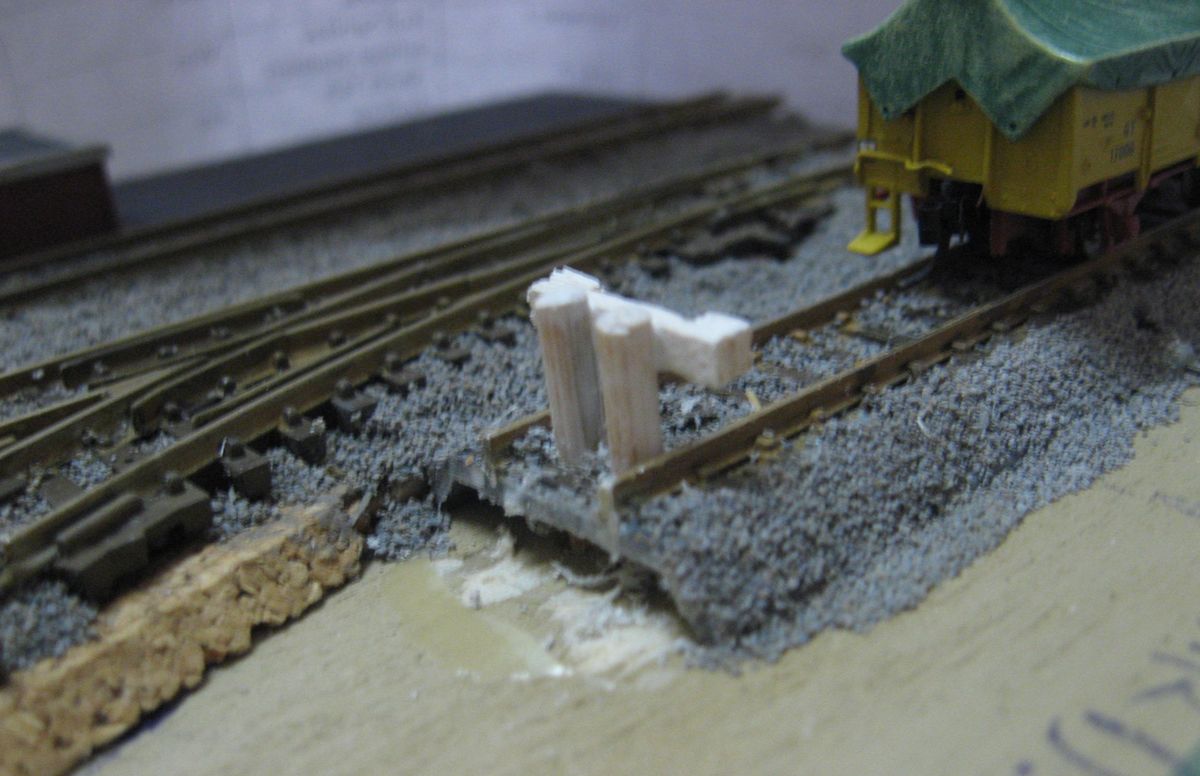
My first construction effort is shown below. The upright posts were cut from bamboo `kebab’ skewers that are about 3mm in diameter. The cross bar is from 1mm and 2mm thick balsa wood sheet I had in the offcuts box. The Kato Unitrack had already had a thin  layer of Woodland Scenics ballast stuck down and so the  drill was deflected slightly on one side and didn’t go as close to the rail as I needed it to, but it still came out O.K. for a first effort.

Image

This the view from the other side.  I need to add another coat of white paint:

Image

The following photo shows a `jig’ that I made out of a 15mm long piece of Evergreen Styrene 6.5mm(1/4 inch) square tube plus some 1mm (0.040″) thick styrene add-ons. This makes placing and assembling the bufferstop very much easier and faster. In this photo the jig is reversed in relation to the bufferstop so that you can see the `ledge’ I created to position the height of the cross beam.

Image

The view below shows the bottom of the jig with a 9mm long piece of styrene centrally located on it to fit between the rails and hold the jig in place on the track. As you can see in the view above.

Image

The next photo is an end view of the jig. The top of the posts scales out to 9.5mm above the top of the SLEEPERS. The code 80 rail is 2mm high, which means that the top of the posts is 7.5mm above the top of the rails. Adding a piece of 1mm (0.040″) thick styrene on top of the Evergreen 6.5mm square tube gives us that desired height above the rails. The bottom surface of the cross bar has to be 3.5mm above the top of the rail, and I added a 3.5mm wide strip of 1mm styrene on the bottom half of one side of the jig to give this height. Image

When in use the `smooth’  side of the jig is placed against the posts to align the top of the posts to the correct height for gluing into place before the crossbars are fitted.  When the glue has set the jig is reversed and the crossbar is fitted and aligned between the jig and the posts. The glue for the crossbar-post joint has to be sparingly applied at the back of the crossbar to avoid sticking the jig to the bufferstop. The cross bar height lines up with the MicroTrains knuckle coupler height.Image

When the glue has set the two small blocks at the end of the crossbar can be applied.
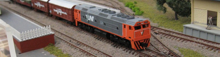
Leave a comment

Filed under Model Railways, Uncategorized

T-TRAK Modules – The single mainline track modules, part the Eleventh – Scenery for the first corner module.

I first became aware of T-TRAK in 2002-2003 and Kato Unitrack was difficult to obtain in Australia. Being in a rural region made it all the more inaccessible. I therefore experimented for a while with my own type of table top modules. Eventually I bit the bullet and went T-TRAK all the way, a decision I have never regretted. This did leave me with some of the earlier type modules, especially the corner module shown below. The scenic work on the hill was particularly satisfying to me and so it sat in storage in the garage for a LONG time.

The following photo’s show how I was able to move the mountain from the old style module to the T-TRAK corner module I have built. The actual hill was formed of expanded polystyrene pieces covered with strips of paper stuck down with diluted PVA glue. This was then covered with a thin layer of cheap acrylic gap-filler, followed by the normal scenic treatments. To protect the outer side of the hill, and also provide a smooth surface to it, I had built up a wall of 3mm MDF along the two outer sides.

I was 99% sure there were no nails holding the polystyrene blocks together or fixing the hill down to the baseboard. Teeth were gritted as I sawed away. My confidence was justified, and the expense of a new saw avoided.

After gluing down the hill formation I used acrylic gap filler to match it into the module base.

To build up some ground height on the inside of the track curve I  fixed down some roughly cut layers of corrugated cardboard.

When the glue had dried I spread out some acrylic gap sealer and revisited finger painting at kindergarten to spread out the gap filler and make a smooth surface. I dipped my fingers in water a few times on the way through and finished off with a wide brush, again dipping into water a few times along the way.

The next few stages were rushed together, not the best move I discovered! Later in the day that I applied gap filler over the cardboard layers I covered it with a coat of brown paint for the basic soil colour. This sealed off the gap filler too early and slowed down the drying time considerably (the result was found out a few days later). A day or so later I fixed down a layer of earth over the new area, liberally applying diluted PVA glue to hold it in place and then topping it off with some coats of Woodlands Scenics ground foam for grass. This looked really good until two days later when I discovered ….

…. that the  acrylic gap filler was still drying (curing?) and has shrunk a little under all the soil and grass cover, resulting in cracks and creases in the scenery. A less to learn: Acrylic gap filler used for ground formations dries out fairly quickly for small amounts, but larger areas need to be left maybe a week or so before putting paints and the other scenic materials on.

Fix it up action consisted of giving a few more days for drying/curing and then lightly coating it with diluted PVA glue sprayed out in a mist via an empty hair care products pump pack. It is important to let the spray gently `mist’ down onto the surface and be soaked up. Ground foam was then sprinkled on via a small sieve and fixed in place with more diluted PVA misting. The results are as follows:

The result is quite acceptable to me and hopefully gives the impression of good `dairying country’. Once I sort out the fencing and some trees  I have a herd of N scale plastic Friesian cows ready to place and help fix the theme of a rural branch line in the southwest of Victoria.

Leave a comment

Filed under Model Railways, Uncategorized

Single Track T-TRAK modules – A sneak preview of postings to come.

While I have not had much opportunity to post on this blog lately I have been getting in a few hours of modelling time over the Christmas-January break. Here are some photo’s of my activities. I hope to get more detailed accounts posted over the next couple of weeks.

Leave a comment

Filed under Model Railways, Uncategorized

T-TRAK Modules – The single mainline track modules, part the Tenth – Putting All 3 modules together.

I managed to get all 3 modules together for a short stint with the camera. The loco and wagon are posed in scenes that I think will be very much the usual operating setting. The corner module needed a bit of height adjustment which I didn’t notice until the end of the photo shoot. Sharp eyes will notice it under the wheels of the guard’s van in the last photo. The next blog will hopefully show some ways to adjust the height of modules.

The station module has had a fair bit of `snow’ fall with the foamcore additions. These build up the ground height around the station tracks as in the prototype the track is frequently at, or near to, ground level. “It is easier to raise the ground than to lower the track.

Overall view of all 3 modules set up. The `down' local goods is entering with an F class shunter (yet to be repainted) very far from it's urban home.

A closer look shows the following wagons in the train. A `GY' open wagon, a 'J' cement wagon, two 'T' refrigerated wagons, another GY, and a `Z' guard's van on the tail.

After splitting the train, the loco has picked up the `B' van from the goods shed and placed into onto the train. It is now placing one of the T vans in the goods yard to be loaded with cheese and butter from the local cheese and butter factory. The other T van is bound for the station at the end of the branch.

This GY is being placed where the superphosphate depot will be.

With the train re-assembled the trusty little F class heads down the branch to the future `end of the line' station.

Having the modules set up like this is a real encouragement to getting back to working on them. Church and family and the Christmas/end of year activities have held me back quite a bit and I found myself hitting mental blocks when it came to starting up scenery work on individual modules.

2 Comments

Filed under Model Railways, Uncategorized

T-TRAK Modules – The single mainline track modules, part the Ninth – Corner Module Woodwork – Part 2. Finishing the woodwork/paint etc and laying track

With the sides of the modules all fixed together I moved on to fitting the  3mm plywood top with fast drying glue and some small nails. My  supply of plywood is  in long pieces of 250mm width, therefore two pieces were needed to cover the top of the corner module. Each piece was fitted  separately and then they were secured together by  gluing an approximately 40mm wide off cut of plywood along the butt joint on the underside. This was held down by a brick whilst drying. See the following pictures:

In our part of the world we have had an incredible amount of unseasonable rain and I made use of a patch of fine weather to next apply the paint (I enjoy working outside when it comes to woodwork and painting). The sides received a coat of `Rivergum’ green (in accordance with the Australian T-TRAK guidelines) and the top was done in “mother earth” to seal the plywood before applying scenery.

When the paint had dried I drilled holes for the 6mm Tee nuts and then hammered them in place. For the adjustable feet I use the plastic feet shown below, usually available in larger hardware stores, or mail-ordered from Timbecon in Western Australia ( Stock description: Adjustable feet, 6mm diameter, Stock number:  ADJF-28). The usual alternative is using normal 6mm bolts.

Where both reasonable and possible I try to recycle track. This is not just for  economic reasons but because local hobby shops are over an hour’s drive away. I had an old non-standard `end-return’ module that had Unitrack at the track ends and Peco flexible track for the most part. The Unitrack was held down with track pins and Selleys Brand “Wet Area Silicon Sealant” which holds the Unitrack securely, especially in the sideways and back and front directions, but does not stick the Unitrack down rock hard.  The Peco track was held down by track pins and the PVA/water mix which holds the ballast in place. After removing all the track pins that I could find I soaked the track with water using three light applications spaced at five minute intervals. After waiting a further five minutes I carefully slid a paint scraper under the track and worked it forwards and steadily lifted up the track. I managed to remove about 75% of the track without damage.

The curve of track for this module has to be 282mm (approx 11 inch) radius. From the old module I was able to recycle one Unitrack 282mm curve section but I also retrieved two 249mm (approx 9 3/4  inch radius) sections.  As these curved sections are all about 10 degrees of curvature or less I used one of the 249mm radius pieces which was slipped off the flexible track to which it was attached. The 282mm radius section had a length of flexible track of sufficient length to reach around the whole curve for the module already inserted in it. It  had also been curved to nearly the correct radius.

I  double checked where the holes drilled in the Unitrack  sections for track pins were and  marked where the edges of the Unitrack base have be located. I then spread some of the Selleys Brand “Wet Area Silicon Sealant” on the module top where the the first section of Unitrack would be laid.Then I held a 1mm thick steel ruler against the module’s edge and slid the Unitrack into position. The silicone sealant plus a bit of deft finger work held the Unitrack in place while I hammered in the track pins, checking the track location after each pin was fixed down.

I then began at the other end of the Peco flexible track. I cut away some of the sleepers from the flexible track and slid the Unitrack base onto the rails (The Australian T-TRAK Guidelines has a section on joining Unitrack to `normal’ code 80 type track, referring to that will  help in  understanding how I am working on this module). Removing the Kato Unitrack Uni-joiner makes life a lot easier at this stage and will allow for trimming the rails a bit later. With the track curved to a good position I found that I still needed to remove some sleeper webbing. I guessed at five sleepers, but found out that I only needed to have taken out four.

While making sure that there was a `good’ curve in the flexible track I fixed down this second piece of Unitrack with Silicone Sealant and track pins. A strip of 3mm thick cork was slid under the flexible track and track pins were used to hold the flexible track in place. I used a Dremel-type motor-tool with cutting disc to cut the rails flush with the end of the Unitrack base. Putting the Uni-joiner back into the track and trimming and sliding in the fifth sleeper I had removed  finished the job. There are some damaged sleepers in the section of flexible track but some trimming and use of strips of balsa wood should fix that.

The scenery plan at this stage is  a low cutting through bushland on the outer side of the curve  and a dairy cow paddock on the inner side, or vise versa.

1 Comment

Filed under Model Railways, Uncategorized

T-TRAK Modules – The single mainline track modules, part the Eigth – Corner Module Woodwork – Part 1.

With the wiring over and done with on the station modules my fingers got itchy on building a corner module so that I can run locos and wagons a bit further than just the very limited  station confines. For this set of modules I am using some materials that deviate from the normal 6mm/9mm plywood or MDF. Australia has a company named Porta Mouldings that manufactures various sizes and profiles of timbers, mainly for decorative trim on furniture and inside houses. After browsing their range in a large hardware store I came across their lengths of DAR(dressed all round) 67X11mm pine in 1.8m and 2.4m lengths, which is made up of shorter lengths `finger jointed’ together  . I also had access to a large amount of 3mm thick plywood. It quickly came to mind that as 67+3=70, placing the 3mm plywood on top of a frame made of the 67X11m pine I would have the correct 70mm height of a T-TRAK module. The Porta Moulding is a tad expensive but that fact that it could be cut easily with my Drop-Saw, or even a hand saw and mitre-box, and that 3mm ply can be cut with a larger sized good quality  craft knife meant that it would be an option for people with limited wood work equipment etc. Worth a try!

T-TRAK corner modules are 365mm on a side and so I cut four pieces of 67X11mm to a length of 354mm. They were assembled so that the 354mm length of each piece was added to by the 11mm thickness of the next piece joining it at 90 degrees. I have a good store of 50mm square wood blocks for  corner blocks and these were glued on to each side section before assembly. Fast drying MDF glue was used, the same stuff that I built the station building kit with. The following photos should explain.

All the wood pieces set up for gluing.

Gluing on the corner blocks.

Gluing the first corner.

Gluing the second corner.

Gluing the third and fourth corners.

John Rumming of Perth, Western Australia, has an excellent article on assembling T-TRAK modules, it is at:

http://home.iprimus.com.au/nuggles58/T-TRAK.html

look for: “A PDF on how to do a T-TRAK module ”

The next post will cover fitting the module top, painting, and placing some track.

2 Comments

Filed under Model Railways, Uncategorized

T-TRAK Modules – The single mainline track modules, part the Seventh – Actual Wiring.

The Australian T_TRAK  (and original standard T-TRAK) double track T-TRAK wiring colours are white for the inner rails and blue for the outer rails of the paired mainlines. On the single track mainline used for these modules the mainline is the equivalent of the `inner’ or `back’ main line of the standard double track T-TRAK module. Therefore the `back’ rail is officially blue and the `front’ rail is officially white. I have updated the ‘Wiring Diagram’ posting to fit in with this nomenclature/description.

The underside of the Goods Shed module. Here I used blue wire for the `outer rail' wiring and yellow for the `inner rail' wiring. This was the only suitable wire I had available at the time. You can also see the RCA sockets I fitted to both the front and back of this module for power input to the modules.

The underside view of the platform end module. Here I used wires of different colours for each appropriate switch.

The actual wiring process was pretty straight forward. I use a 40 Watt soldering iron that usually get the job done quickly. There are web-site around that can take you through soldering process a lot better (both in explanation and technique) than I can. To make soldering easier I use a flux applied with a small cheap (ie almost disposable) paint brush. The flux I chose IS NOT CORROSIVE  AND DOES NOT NEED RINSING OFF, it is “Broad gauge Models” low melt solder flux. Again, check with the more expert web-site for more information on this.

Access to the terminals of the slide switches can be a bit cramped inside the module. After my experience I recommend that you attach small lengths of wire to each terminal BEFORE fitting the switch in place.

Leave a comment

Filed under Model Railways, Uncategorized