Tag Archives: N scale

Sadler’ Sidings – 05 – Some merchandise on Shed A platform.

G’day Folks, An update on Sadler’s Sidings.

First an extra building next to ‘Shed A’ cobbled together out of old POLA kit parts. It will become either a workshop for Sadler’s or a separate business leasing the building.

SAdlers Shed A 15-05-15-1 1200W

SAdlers Shed A 15-05-15-3 1200W

Second, some pallets with merchandise are now on Shed A’s platform, I will follow up exact details later on my Pallets post in N Gauge Forum:
http://www.ngaugeforum.co.uk/SMFN/index.php?topic=27624.msg302171#msg302171
Please note that I am not overloading the platform. In real life a well functioning and efficient  warehouse operation would keep lots of items on the move or stored away in its proper place. Otherwise not only is there confusion and delay, it is very dangerous and limiting to workmen and forklifts etc.

SAdlers Shed A 15-05-15-2 1200W

2 Comments

Filed under Model Railways, shunting layout

Some more wagons for Sadler’s Sidings

G’day Folks, I’ve been working on rollingstock lately.

First off I’ve rebuilt one of my old Fybren Models ELX open wagon kits. I shortened it to fit under an Aust-N-Rails ELX resin tarpaulin. I then fitted shunter’s steps made out of folded brass ladders and small rectangles of styrene. Then followed them up with some folded staples for other bits and a styrene rectangle for the logo. Paint was Humbrol 113(?) carefully brushed on and then followed by two light coats of hardware/discount store spray paint. Decals are a mixture of G&R and Bills Billboards. The VLX is also a rebuilt Fybren kit fitted with a Spirit Design underframe with details etc much the same as the ELX except only spray paint used for VR oxide red. White paint is Tamiya acrylic white carefully brushed on. Others have done far better than I with these models, but I am satisfied with them as `shunting fodder’.

VOCX & VLX - 1200pxl

The green van is an N-TRAINS NSWGR HLX that in my theoretical world has been bought by Sadler’s as a private owner in captive service on the broad gauge. Tamyia spray can paint for this beastie. Will work on decalling and details sometime as I want it to resemble the prototype Sadleirs vans, but not be an exact copy.

 Sadlers Van & VLX - 1200pxl

Leave a comment

Filed under Model Railways, shunting layout

Sadlers Sidings – 04 – Laying track on a SideTrack Module

G’day Folks, I have some photos and commentary on laying track on the Sidetrack modules.
The quality of some photos may be a bit below par due to being taken outside, at night, under a single light, on our front verandah, when day to day life events and temperatures allowed me to work.
The photos come from the laying of track on two 160mm wide and 250mm track length modules (248mm woodwork length). The displayed sequence is correct although the photos may alternate between the two modules. The 160mm width is to allow for some more space for either 3 tracks or industrial structures behind the rear track. The 250mm length is partly because of the single point on the 2 to 3 track transition module and because I was starting to run out of room on the table! I will play around with ideas for corner modules a bit later.
First off, PAINT the modules to seal them, both outside and inside.
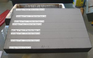
Then mark out the edges of the track locations for the Kato Unitrack which has a 25mm width on its plastic ballast, and which for Sidetrack using Peco Set-Track points has a 35mm track centers.

Marking out Track locations

Marking out Track locations

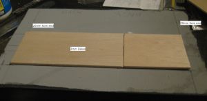
Next mark out two lines 20mm from the ends of the modules and running parallel to the ends. Then stick down sheets of 3mm thick balsa wood between the two new lines and at the total  width of the number of tracks you are going to lay. This forms a roadbed/underlay for the conventional N gauge track so that its height matches the Kato Unitrack. When glue has dried, paint!

3mm Balsa roadbed

3mm Balsa roadbed

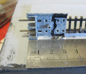
Taking your 30mm (or so) long piece of Unitrack (in this case it’s just the Unitrack base threaded on to some existing flexible track) and on the underside mark out a line 20mm from the Unijoiner end.

MArking out Unitrack end piece for trimming of Ballast slope

Marking out Unitrack end piece for trimming of Ballast slope

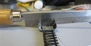
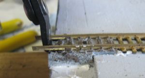
Turning the Unitrack upside down, cut through the ballast slope edges of the Unitrack until you touch the actual track base.

Cutting off ballast Slope Cut 1

Cutting off ballast Slope Cut 1

Then from the top cut off the sloping ballast edge until you reach the transverse cut.

Cutting off ballast Slope Cut 2

Then break off the ballast slope.

Cutting off ballast Slope Breaking off ballast slope

Cutting off ballast Slope Breaking off ballast slope

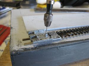
When you have done this for both sides drill holes for the track pins. The first hole is drilled through the hollow column under the Unitrack, This is Kato’s built in fixing point.

Drilling for track pins 1

Drilling for track pins 1

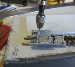
Then on both sides of the track drill holes in the corner between the outside of the Unijoiner pockets and the beginning of the ballast slope.

Drilling for track pins 2

Drilling for track pins 2

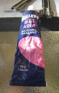
Take some Silicon Wet Area Sealant, or similar, to use as a glue for the track. This wonderful stuff feels weird on the fingers, does actually hold the track down, and yet will peel or rub of when you need to get rid of it.

Silicon Wet Area Sealant

Silicon Wet Area Sealant

Apply three dabs of the Silicon sealant in the spots shown.Ber careful to keep the area where the Uni-joiners go clear of sealant, tricky, but necessary.

Applying Silicon Caulk

Applying Silicon Caulk

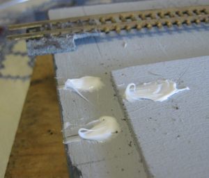
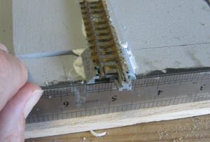
Locate the track into its position and push down into the Silicon paste. Use a 1mm thick steel ruler to allow you to work out the 1mm overhang.

Fixing down Unitrack End 1

Fixing down Unitrack End 1

Carefully push a track pin in to the first drilled hole. Then follow this with pushing in two more track pins into the other two holes. Because of the wood frame these last two pins will not push all the way down. Carefully using a nail punch hammer the pins into the wood frame.

Fixing down Unitrack End 2 Track Pins

Fixing down Unitrack End 2 Track Pins

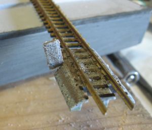
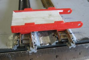
When you have let the first piece of track set in the silicon for a few hours you can locate and fix down the adjacent piece of track using a jig made out f two Peco track spacing jigs.

Fixing down Unitrack End 3 Using track spacing jig

Fixing down Unitrack End 3 Using track spacing jig

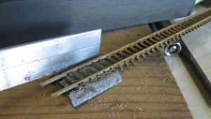
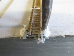
Because this end of the track has some rail sticking out the end I used Xuran Track Cutter to trim it back to length.

Fixing down Unitrack End 4 Xuron Rail cutter to trim ends

Fixing down Unitrack End 4 Xuron Rail cutter to trim ends
All done for 2 tracks

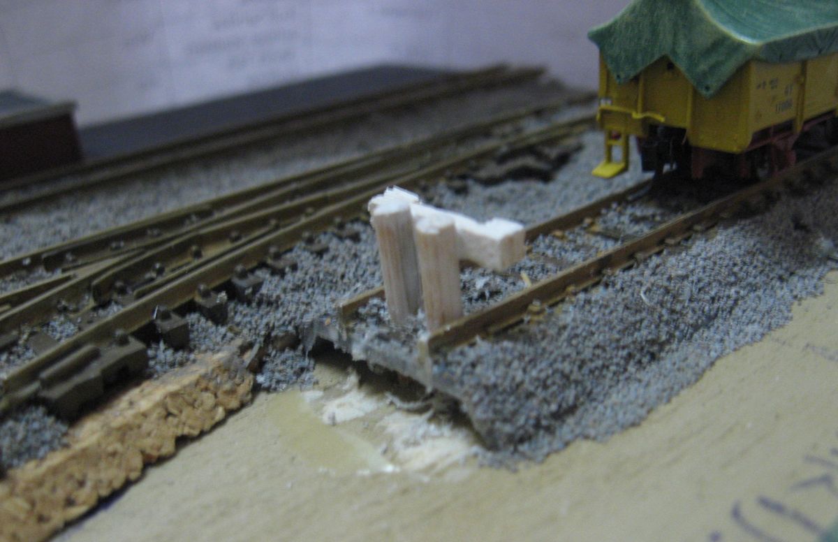
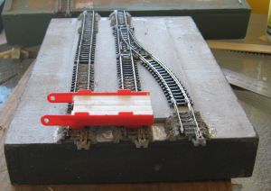
How the other module ended up.

SideTrack 2 to 3 Track Transition 1

SideTrack 2 to 3 Track Transition 1
SideTrack 2 to 3 Track Transition 2

For all sorts of tips and tricks for fitting Unitrack in with conventional gauge track go to pages 19 to 21 of the Australian T-TRAK Guidelines at:
http://t-trak.nscale.org.au/guidelines

Leave a comment

Filed under Model Railways, shunting layout

Sadler’s Sidings – 03 – Building a `Sidetrack Module’

G’day All, This post covers the making up a 160mm wide (125 +35) and 248mm long (multiple of 50mm less 2mm for Unitrack overhang) Sidetrack Module. i.e. this module will allow for three parallel tracks.

This is a ‘pull saw’ that makes cutting timber a dream. It takes a little getting used to and really requires that you let the saw do the cutting and not your pushing down on the wood:

Implement of separation

Implement of separation

A comparatively cheap plastic mitre box that does the job well if you don’t hurry:

Mitre Box

Mitre Box

Even though there is the mitre box to keep cuts square, marking them as square is a good habit that pays dividends in future work:

Marking the wood

Marking the wood

While the sides were cut to the full length of the module (248mm) the ends were cut to fit inside the sides to give a neat outer appearance. This means that the ends have to be cut to a length of  160mm less the combined width of the two side pieces. Don’t rely upon the theoretical widths, measure the real ones. Sidetrack, and its original T-TRAK,  can tolerate small errors (see down further), but sensibly keeping them to a minimum doesn’t stretch that tolerance:

Measuring combined width of both side pieces

Measuring combined width of both side pieces
Frame components placed out for assembly
Gluing corner blocks ot end pieces
Gluing corner blocks to end pieces
Clamping sides to ends

As you can see there are a couple of ‘ooops!’. Width is 161mm but that is less than 1% error and the `wonky’ corner was straightened up before the glue had set:

Checking the width

Checking the width
Frame finished
Frame finished

This end piece is an off cut from a previous module’s construction. One side was `dead on’ for the width, the other was 1mm too short. A bit of careful alignment of the corner blocks and it was overcome. Not recommended for your first few modules unless you are really limited on timber to hand:

Weird End Yankovic

Weird End Yankovic
Weird End overcome
Weird End overcome

3mm balsa for the top of the module. I find that prices here in Auz can vary quite a bit between individual shops and towns. There is no place to buy it in my own home town and so if my own stocks are low I purchase sheets when I see them:

3mm Balsa sheet

3mm Balsa sheet
Balsa top 2 panels clamped

The reinforcing spine was another offcut from previous work and I had apples stewing on the stove. No one will see it, except you dear reader(s):

Reinforcing spine fitted

Reinforcing spine fitted

An update to fitting the spine, make sure that you have worked out your track plan in terms of under the baseboard items before fitting the spine. I have had to remove this one to allow for an under the baseboard drop away magnetic uncoupler. I will refit the spine once clearances are worked out.

Leave a comment

Filed under Model Railways, shunting layout

Sadler’s Sidings – 02 – The Basic Modules – Drawings

G’day All, The modules that form Sadler’s Sidings have been developed over a couple of years of playing around with wood moldings, plywood, balsa sheet and other stuff in order to create a robust and light table top modular system which is suited to quick set up on the kitchen or living room table and is easily stored away. The T-TRAK modules are excellent for most purposes, as my working with them for over 10 years proves, but when it came to creating a small switching layout that could also be packed into comparatively small boxes even T-TRAK modules were too large. I also had in my mind my days as a tertiary student living in student accommodation and shared houses where most major woodworking tools were hard to store and use. These modules can be built using glue, small clamps, small mitre box, small saw, craft knife, steel ruler etc and the materials can be bought at hardware and hobby shops.
If they develop into a modular system it will be known as `SideTrack’ to fit in with the concept of making shunting layouts that feature sidings rather than a main line or branch line focus.
Basic 300mm by 125mm Side Trak 35 Module - frame & top top view 11mm
Basic 300mm by 125mm Side Trak 35 Module frame & top top view 11mm

The basic frame, reinforcing spine and corner blocks are all off the rack timber moldings. I first used pine moldings but have found that they are often a millimeter two smaller than the stated dimensions. Hardwood moldings appear to be more consistent.
The top surface is 3mm thick balsa wood mounted with the grain running across the width of the module to gain maximum strength. 3mm ply could be used but it is a real pain to cut with a craft knife compared to balsa.

Basic 300mm by 125mm Side Trak 35 Module - frame & top 11mm upside down

Basic 300mm by 125mm Side Trak 35 Module frame & top 11mm upside down

VERY IMPORTANT: Do not fix the central `spine’ until you have mapped out where you will have under the surface items, eg. magnetic un-couplers, switch(point) motors etc. You may need to move the spine to make clearance ofr them, as I discovered the hard way!

The width of 125mm just `worked out’ as I considered balancing the need for space for the actual industries against the need to have comparatively narrow modules for easy storage. The O scale equivalent width is 500mm and the experts in that scale can create quite adequate shunting layouts with that dimension – eg. Bury, Thorn & Sons at:
http://www.rmweb.co.uk/community/index.php?/topic/15931-bury-thorn-sons/
Basic Sidetrack Module 125mm wide

The length of a module is a multiple of 50mm less 2mm to allow for the Kato Unitrack to overhang the ends by 1mm at each end.
The next BLOG post will be photographic description of actually building one of these modules.

Modify message

« Last Edit: February 27, 2015, 04:05:28 am by T-TRAK_Andrew »

Leave a comment

Filed under Model Railways, shunting layout

Sadler’s Sidings – 01 – An N scale table top shunting layout that uses T-TRAK/Unitrack technology.

G’day Folks, Back into it at last. Sadler’s Sidings is my current really active project. It is a table top modular shunting layout that uses T-TRAK/Unitrack technology to join 3 by 300mm long modules plus a 100mm long ‘end of the line module’ and two clip on bufferstops. Sadler's Sidings for NGForum Sadlers Sidings 2015 02 10 Long view The basic concept is focused around a freight forwarding company  called ‘Sadler’s Freight Forwarding’. I chose the name Sadler’s for two main reasons.  Firstly there is the prototype Sadleir’s Logistics who make use of regular rail service with their sidings in Melbourne, Perth & Sydney. See: http://www.sadleirs.com.au/sadleirs-logistics/interstate-road-rail.  Secondly, my grandmother on my mother’s side was a Sadler who migrated out to Australia from England early last century. By using that spelling I can capture the flavour and concept of the prototype operation  without issues of trying to be `accurate’. The layout is to represent a Sadler’s rail depot in the industrial area of a major city where there has been an original corrugated iron warehouse and as business has grown adjacent buildings have been occupied and renovated or replaced with more modern construction. Other industries and goods transfer areas will occupy the rest of the layout. Future expansion is always a possibility  and is very likely once I have goth the 3 main modules up to a reasonable level of scenery and structures. To see the Sadleir’s prototype operations in Google Maps and Bing Maps the street addresses are: PERTH: 75 Leach Hwy,Kewdale WA 6105 MELBOURNE: 525 Geelong Rd,Brooklyn VIC 3012 – Old Site now closed 550 Melbourne Rd, Spotswood VIC 3015 – New site, bo9th Google Maps and Bing Maps show views of old rail workshops on which the new depot is built. Photos of new site – http://www.railgeelong.com/gallery/newport-sunshine/spotswood-depot/ SYDNEY: 113-115 Punchbowl Road Belfield, New South Wales 2191 The overall scenery style is to be generic Australian. While I intend to operate Australian prototype rollingstock most of the time there will be sessions when I will break out my British, European and Japanese items and go IRWIL mode. (IRWIL – I Run What I Like). Sadlers Sidings 2015_02_10 _14Sadlers Sidings 2015_02_10 _16 Sadlers Sidings 2015_02_10 _09 Sadlers Sidings 2015_02_10 _07Sadlers Sidings 2015_02_10 _08 Sadlers Sidings 2015_02_10 _06One of the aspects of T-TRAK type modules is the 2mm gap that appears  between them because of the Unitrack overhang. On the usual T-TRAK situations the flow of scenery and general viewing angles normally reduces the effect, but in a table t0p situation where the operator is sitting only tens of centimeters from the modules the gap becomes more noticeable. My trial effort at closing the gap is to apply 5mm wide strips of approximately 1mm thick `craft foam’ along the ends of each module under the projecting edge of the Unitrack. The craft foam is compressible like neoprene and so it should be able to absorb any woodwork/overhang  problems. It should also be able to handle a coat of paint on the edge along with a light application of ground foam/static grass without losing the compression. T-TRAK Gap Filler 02 T-TRAK Gap Filler 01

5 Comments

Filed under Model Railways, shunting layout

T-TRAK Modules – The single mainline track modules, part the 13th – more work on the station platform.

Well after quite a few months I am back at the keyboard and updating on the VR Branch single track T-TRAK modules.  The last installment (Part the 12th) showed the platform walls being put in place along with a styrene sheet top for the platform. This sheet is recessed below the platform edge so that scenic material could be spread over the top. As I thought through the overall shape of the land around the platform and spent a few hours researching photos of smaller rural stations I ended up trimming the styrene sheet back quite a bit to allow a good amount of sloping ground on the road side of the platform while keeping enough of it to place the station building on a level surface. I have a small supply of blue EXTRUDED polystyrene insulation foam and made use of it for the basic land forms. It is wonderful stuff to work with for this type of job.

Station platform with blue foam earthworksIn the following 2 photos you can see how I am making room for a small gangers’ shed.

Station platform with blue foam earthworks 02You can also see in the above and below photos that I am experimenting with alternative scenic material for soil. This is bought about by the decision to model the Otways area of Victoria where the soil is very much more brown than what I was first contemplating. This will mean a reworking of the other station module’s scenery.

Station platform with blue foam earthworks 03In real-time reality I am a bit further on scenically than these photos depict and hopefully I will update you with more photos in a week or two.

Leave a comment

Filed under Model Railways, Uncategorized

Unloading Ramp for use by Forklifts

Image

Back in 1983 in the Melbourne suburb of Dandenong I photographed a set of metal sided sheds and a portable wagon unloading ramp where forklifts were used to unload palletised bagged cement from railway wagons for transfer to road trucks and/or the storage shed(s). A few days ago I had the opportunity to go through my highly disorganized slide collection and finally located the photos. They are beginning the inevitable degrading of age, and with my `economy’ slide scanner, I have some passable scans. The first is shown above.

Another view of the ramp is at: http://www.flickr.com/photos/60901191@N08/6000939201/in/photostream/

As I learn more about Google SketchUp I am getting better at making plans from photographs. As I get my brain back into `can do’ mode I am getting better and converting plans in to objects. The results are as follows:

Image

ImageImage

Image

Some of the horizontal railings are in need of re-alignment and there is only the first coat of paint on the model, but I am happy with the overall result as this my first completely scratchbuilt item in a long time.

3 Comments

Filed under Model Railways, Uncategorized

Bringing it all together – Almost finishing one shunting module.

After waxing lyrical on various subjects over the past few posts I thought it was time to show how I am bringing them together with the shunting modules. I am experimenting with.

This is a reworked GreenMax factory kit. The real Armstrong Engineering was owned and operated by my father-in-law and was a smaller and non-rail served premises, but when the building came into place on the module it felt very right to name it so.

Overall view of the join between the `Armstrong Engineering’ module and the “Saddlers’ Interstate Forwarding” module.

Overall view from one end of “Saddlers’ Interstate Forwarding” Module. Saddlers’ Interstate Forwarding is a name variation on Sadleirs Logistics that use rail and road for freight movement from Sydney and Melbourne to Perth. This is a very much shrunk down version from a POLA kit I had on hand. I still have a few `fiddly bits’ to finish off on this module.

Close up of the platform at Saddlers Interstate Forwarding.

Some ground work and electrostatic grass and the new bufferstop is looking very much at home.

Roast for dinner???? Not with these little black ducks!!!

5 Comments

Filed under Model Railways, Uncategorized

Making an end of it … the end of the track that is! A.K.A. Bufferstops and one way to make them.

G’day again. In both the model and real world railway rollingstock have the uncomfortable, inconvenient, and very dangerous habit of rolling of the end of the tracks unless there is something there to stop them. The answer is to place something at the end of the track to stop this happening. Railways all over the world have worked on various designs depending upon finances and materials available, the likely hood of a runaway or over run, and the momentum of any likely offender(s). These devices can be called `bumpers’, `track bumpers’, ‘buffers’, ‘bufferstops’,  and probably a few other names that I have yet to hear. At the bare minimum they can be simply a pile of dirt or old ballast over the rails or an old sleeper or short section of rail fixed down across the running rails and placed at the end of a low use siding. At the other end of the spectrum they can be hydraulic/oil filled shock absorbing structures placed in a busy passenger station. Between these two extremes is a whole continuum of designs, materials and construction methods.

One of the standard designs of the old Australian state government run Victorian Railways can be found at Mark Bau’s Victorian Railway web site:

http://www.victorianrailways.net/infastuct/infastructhome.html

hiding amongst the `F Series’ plans as F 243b.

Using Google Sketch Up I have made a drawing of the basic dimensions for a 1:160 scale model. Click to open the following file.

VR Buffer stop draft 4

This design fits BETWEEN the rails and BETWEEN the final sleepers at the end of the track. Hence the 10mm extreme width of the pair of posts for VR broad gauge. For 9mm gauge I bring the posts closer together and reduce the width of the cross bar by 1mm. The height dimension is from the TOP of the SLEEPERS.

My first construction effort is shown below. The upright posts were cut from bamboo `kebab’ skewers that are about 3mm in diameter. The cross bar is from 1mm and 2mm thick balsa wood sheet I had in the offcuts box. The Kato Unitrack had already had a thin  layer of Woodland Scenics ballast stuck down and so the  drill was deflected slightly on one side and didn’t go as close to the rail as I needed it to, but it still came out O.K. for a first effort.

Image

This the view from the other side.  I need to add another coat of white paint:

Image

The following photo shows a `jig’ that I made out of a 15mm long piece of Evergreen Styrene 6.5mm(1/4 inch) square tube plus some 1mm (0.040″) thick styrene add-ons. This makes placing and assembling the bufferstop very much easier and faster. In this photo the jig is reversed in relation to the bufferstop so that you can see the `ledge’ I created to position the height of the cross beam.

Image

The view below shows the bottom of the jig with a 9mm long piece of styrene centrally located on it to fit between the rails and hold the jig in place on the track. As you can see in the view above.

Image

The next photo is an end view of the jig. The top of the posts scales out to 9.5mm above the top of the SLEEPERS. The code 80 rail is 2mm high, which means that the top of the posts is 7.5mm above the top of the rails. Adding a piece of 1mm (0.040″) thick styrene on top of the Evergreen 6.5mm square tube gives us that desired height above the rails. The bottom surface of the cross bar has to be 3.5mm above the top of the rail, and I added a 3.5mm wide strip of 1mm styrene on the bottom half of one side of the jig to give this height. Image

When in use the `smooth’  side of the jig is placed against the posts to align the top of the posts to the correct height for gluing into place before the crossbars are fitted.  When the glue has set the jig is reversed and the crossbar is fitted and aligned between the jig and the posts. The glue for the crossbar-post joint has to be sparingly applied at the back of the crossbar to avoid sticking the jig to the bufferstop. The cross bar height lines up with the MicroTrains knuckle coupler height.Image

When the glue has set the two small blocks at the end of the crossbar can be applied.

Leave a comment

Filed under Model Railways, Uncategorized